Thesis
My thesis project is testing the deflection of flat oval shaped spiral ducting. The first step was to build a truss system to hold the duct.
Truss
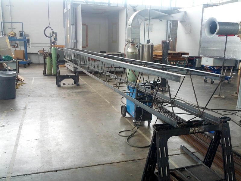
 The truss is a 16 inch warren box truss, which is 24 feet long. I calculated it should only deflect about five hundredths of an inch with 500 pounds hanging from it. This calculation included the truss weight, which is about 200 pounds. Though this calculation was a simple back of the napkin calculation, it worked for my purposes.
Since I already had the welding jigs, I used a 16 inch truss to suspend the entire system off the floor. There turned out to be about 400 three-eighths inch rods in the truss. They were all cut with bolt cutters and placed in the truss before being welded. The truss was welded in sections then bolted together in case the system needed to be moved.
The truss is a 16 inch warren box truss, which is 24 feet long. I calculated it should only deflect about five hundredths of an inch with 500 pounds hanging from it. This calculation included the truss weight, which is about 200 pounds. Though this calculation was a simple back of the napkin calculation, it worked for my purposes.
Since I already had the welding jigs, I used a 16 inch truss to suspend the entire system off the floor. There turned out to be about 400 three-eighths inch rods in the truss. They were all cut with bolt cutters and placed in the truss before being welded. The truss was welded in sections then bolted together in case the system needed to be moved.
 It took a lot of people to assemble the truss system, because our forklift was out of commission at the time. The plywood box makes the rolling jack tall enough to lift one end of the system so it can be moved, or the beams can be bolted. Luckily, we have two jacks and two boxes.
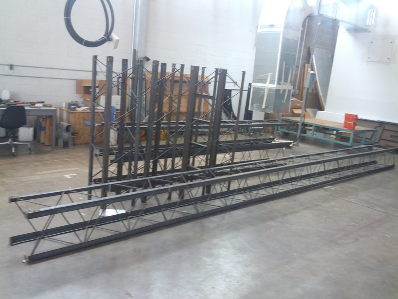
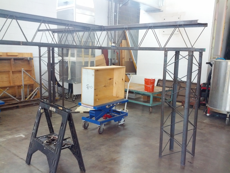
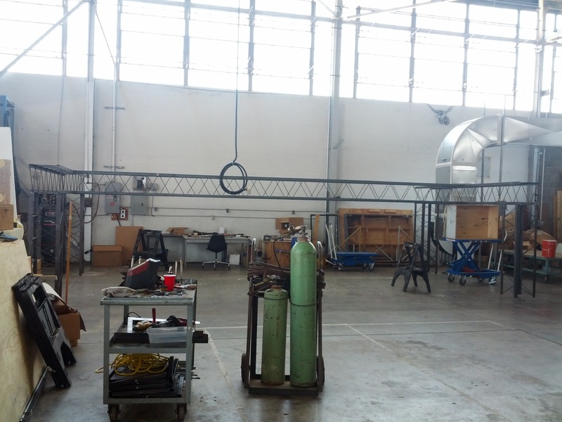 The truss has performed extremely well. No noticeable sag occurred and objects attach easily to it. Due to these features, this truss system is also going to become a leakage test facility and a barrel fan test facility. Because objects easily attach to the truss, I use it for painting, storage and wire runs.
Fork lift
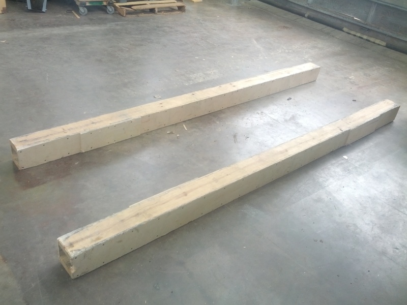 I had to build wooden fork extenders for the fork lift because standard length forks will not carry the duct samples, which are made of two 12 foot sections. These extenders are great because they are extremely light and strong. They are slick so sliding the duct around on the extenders are easy. Being square, they seem to not leave little dents in the duct like the round ones we first used.
Air Pressure
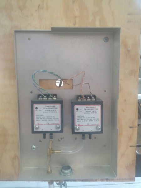
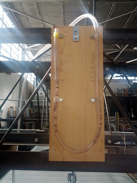 The pressure transducers used are 0-10 inch pressure with an accuracy of 0.25% FS. Two of them were created, one for negative tests and one for positive tests. I made a manometer, which serves two purposes. First, it is a double check for the pressure gauges to make sure they are in the ball park, and second it is a pressure relief valve for the duct in case it is pressurized to over 11 inches of water. The manometer's use as a pressure relief pathway explains the large size of its hose.
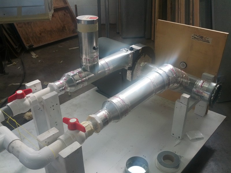 This blower can do 10 inches of pressure. When the valves are turned and the caps are switched, the blower can go from positive pressure to negative pressure. This blower is controlled by a VFD, which gets its control signal from a voltage output board controlled by my computer program.
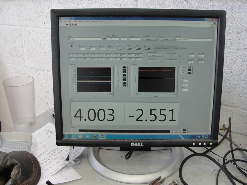 This program serves two purposes. First, it controls the blower with a PID controller to pressurize the duct to the desired pressure. It also records the potentiometer measurements. This program was written in Labview and exports the data to CSV files, which Excel imports with a macro to analyze and draw graphs.
Measurement
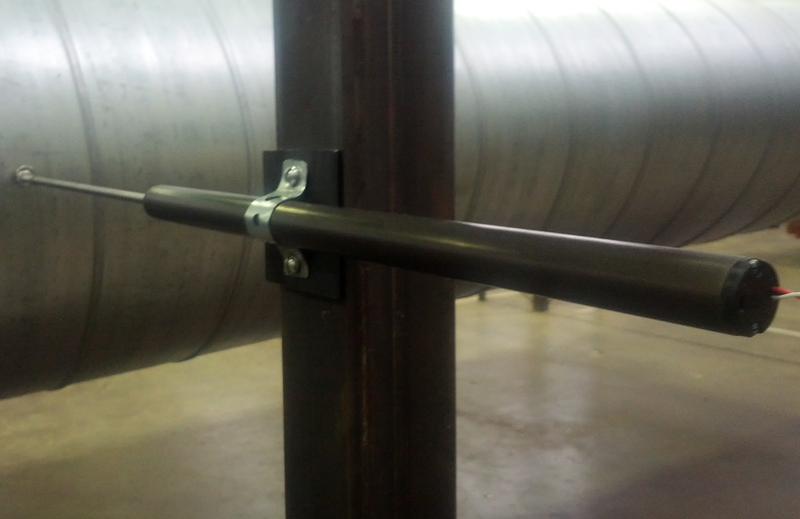
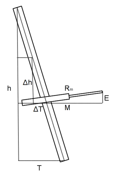 The 10 inch linear potentiometers are accurate to about 0.01 inches. The standard requires 1% accuracy on the deflection measurements. When first installed, the potentiometers had radio interference problems, but when I rewired them with cat5, this problem went away. The accuracy of the potentiometer is highly dependent on how vertical the post is since the potentiometers have to be slid up and down the post to stay inline with the axis of the duct. When pressurizing, the duct's second moment of inertia changes causing it to rise and sink.
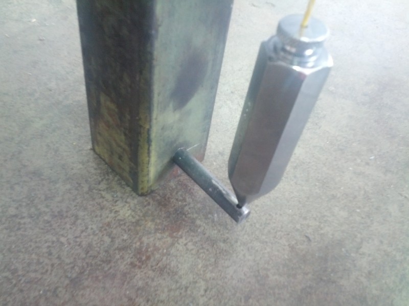 Plumb-bobs are used to ensure the vertical accuracy of the posts.
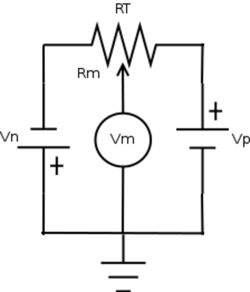 This is how the potentiometers are wired. This gives me the most accuracy because it increases the voltage across the potentiometer even with my DAQ only reading -10 volts to 10 volts.